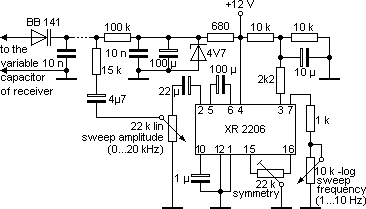
Sweeping - The extended Radio Methodby Peter Stein, DemarkIt was almost eight years ago, when I had – inspired by various observations during EVP recordings by radio – the idea to "sweep" radio receivers. Right from the beginning I was amazed by the extraordinary good results of this EVP recording method. I worked with sweep recordings for several years, but the first time I mentioned this towards other researchers was (as far as I remember) at a meeting in Vienna in Spring 1988 and later in Fulda. Since that time I'm being asked about this EVP recording method every now and then, and even "sweep cassettes" have been sent to me for analyzing and confirming voices. In the course of this some misunderstandings became apparent as to what sweeping actually means, and since I – as already mentioned – had good results with this method, a detailed description of the "what" and "how" might perhaps be of interest. The technical term "sweeping", which is well-known in electronics, means to automatically move the tuning between two fixed frequencies back and forth. The distance between these frequencies is called "sweep amplitude", the speed of the back and forth movement is called sweep frequency, and both of them are usually adjustable within certain limits. Sweeping a radio receiver now is done by moving the scale pointer back and forth over a defined (small) frequency band. An example: The receiver is tuned to Radio Vatican (1530 kHz). By using a sweep amplitude of ± 10 kHz, the tuning of the receiver would move back and forth between 1520 and 1540 kHz, i.e. over Radio Mainflingen and Radio Kosice. This happens with a speed of 4 Hz, which is adjustred to four times a second. Now assume that these three radio stations all transmit voice transmissions at the same time. You would hear a mixture of Italian, Slovakian and German, and all these languages would alternately blend into each other. In this mixture, EVP are formed very often – voices independent from the background, the mode of speaking peculiarly linked to the sweep rhythm. The voices arise through the actual sweep movement, and it's a misunderstanding to believe that it's possible to produce a "sweep cassette" for subsequent application. This can be done just as little as one can spare somebody gymnastics by watching a gymnastics video. Now how is it done technically? What you need are two very simple constructions: 1. A receiver with a sweep connector, i.e. an input which allows to vary the tuning by applying a voltage. 2. A sweep generator. This is a device which provides a slowly increasing and decreasing voltage and thereby can alter the receiver tuning by a certain amount and with a certain speed (sweep amplitude and sweep frequency). To do an EVP recording, you first find a radio station or a mixture of stations, preferably all voice transmissions, with the sweep amplitude turned to the minimum. Next you slowly increase the sweep amplitude, and maybe alter the sweep frequency. The whole thing requires a some experience, but after a few attempts it will work very easily. A schematic of a simple sweep generator as well as the necessary modifications to the receiver are included here. Currently we're doing experiments with a small, simple SW sweep receiver, and also the possibility to construct a sweep supplement for the Psychophon is being examined. More about the sweep method will follow in the next issue of the VTF-Post, interest in this matter provided. On the next VTF convention in Fulda there will be a chance to take a closer look at the devices and to debate on potential questions. * * * Instead of the original schematic of the sweep generator by P. Stein, we will present and describe here another tested schematic. It's a supplemental device which fits onto a small board of only a few square centimeters in size and thus can easily be built into an existing radio receiver. The two potentiometers for the sweep amplitude and sweep frequency have to be mounted at an appropriate place of the casing.
It's important that the varactor diode BB 141 (capacity ca. 20 pF) and the 10 nF capacitor between the cathode of the diode and ground is soldered directly to the variable capacitor of the oscillator stage of the receiver. The diode is connected to the "hot" end of the variable capacitor, the capacitor to the "cold" end (ground). This additional capacity must be compensated by decreasing the trimmer capacitor of the oscillator stage. The wires between diode/capacitor and sweep generator should be as short as possible. The ground of the sweep generator must be connected to the ground of the receiver, the supply voltage for the sweep generator is taken from the power supply of the receiver. The integrated circuit XR 2206 is a function generator which is wired as a saw tooth generator; but any other circuit which generates a sine or triangle signal of some volts and a frequency of 1...10 Hz is applicable as well.
|


